You are currently viewing an archived version of Topic Vertical (Geopotential) Datums.
If updates or revisions have been published you can find them at Vertical (Geopotential) Datums.
The elevation of a point requires a reference surface defining zero elevation. In geodesy, this zero-reference surface has historically been mean sea level (MSL) – a vertical datum. However, the geoid, which is a particular equipotential surface of Earth’s gravity field that would coincide with mean sea level were mean sea level altogether unperturbed and placid, is the ideal datum for physical heights, meaning height associated with the flow of water, like elevations. Tidal, gravimetric, and ellipsoidal are common vertical datums that use different approaches to define the reference surface. Tidal datums average water heights over a period of approximately 19 years, gravimetric datums record gravity across Earth’s surface, and ellipsoidal datums use specific reference ellipsoids to report ellipsoid heights. Increasingly, gravity measurements, positional data from GNSS (Global Navigation Satellite System), and other sophisticated measurement technologies GRACE-FO (Gravity Recovery and Climate Experiment – Follow On) are sourced to accurately model the geoid and its geopotential surface advancing the idea of a geopotential datum. Stemming from these advancements, a new geopotential datum for the United States will be developed: North American-Pacific Geopotential Datum 2022 (NAPGD2022).
Author and Citation Info:
Kessler, F. (2022). Vertical (Geopotential) Datums. The Geographic Information Science & Technology Body of Knowledge (2nd Quarter 2022 Edition). John P. Wilson (Ed.). DOI: https://doi.org/10.22224/gistbok/2022.2.4
This Topic is also available in the following editions: DiBiase, D., DeMers, M., Johnson, A., Kemp, K., Luck, A. T., Plewe, B., and Wentz, E. (2006). Vertical datums. The Geographic Information Science & Technology Body of Knowledge. Washington, DC: Association of American Geographers. (2nd Quarter 2016, first digital)
CORS – Continuously Operating Reference Station. Although not obviously stated, this phrase implies a GNSS reference station minimally composed of: GNSS antenna, GNSS receiver, data storage, and power. Most often a station will not only continuously log satellite data 24/7/365 but will utilize onsite communications to automatically send the logged data to a station manager. This station manager may be a person, a team, or a computer, and may be responsible for management of a single CORS or even a network of thousands of CORS. .
Ellipsoidal vertical datum – A surface that uses a reference ellipsoid and six geocentric parameters expressing origin, and orientation and provides the foundation for accurate determination of ellipsoidal heights.
Equipotential surface – A surface with the same potential (usually of gravity or of gravitation) at every point. Since the potential is the same at every point, no work is done when a body (point-mass) is moved about on such a surface. An equipotential surface is also referred to as a level surface.
Geodesy – The science concerned with determining the size and shape of the Earth. Of relevancy here is physical geodesy which is concerned with Earth’s gravity field.
Geodetic vertical datum – A surface that employs Earth’s gravity field as the zero-reference surface.
Geopotential surface – A surface on which Earth’s gravity potential is constant (synonymous with equipotential surface.
Geopotential value (W0) – The difference between the geopotential on the geoid and the geopotential at a point.
GNSS – Global Navigation Satellite System. A general reference to any artificial satellite system that uses a constellation of satellites to provide autonomous geospatial positioning.
GPS – Global Positioning System. The official United States government artificial satellite system that provides autonomous positioning. Operated by the United States Department of Defense, notably the 50th Space Wing of the United States Air Force.
Gravimetric geoid model – A geoid model derived from direct or indirect measurements of gravity on Earth’s surface.
GRS80 – Geodetic Reference System of 1980. The name of a global geocentric reference ellipsoid with the following conventional constants for the equatorial radius of Earth: a = 6,378,137 m and a flattening of f = 1/298.25722210. Values of a and f were taken from the European Petroleum Survey Group’s Geodetic Parameter Dataset (www.epsg.org).
Hybrid geoid model – Used to convert ellipsoid heights derived from GNSS to orthometric heights.
IGLD - International Great Lakes Datum. The official vertical datum used to measure and report water level heights in the Great Lakes, their connecting channels, and the St. Lawrence River system. Established and revised under the auspices of the Coordinating Committee on Great Lakes Basic Hydraulic and Hydrologic Data, comprised of representatives from various United States and Canadian Federal Government agencies.
Leveling – The process of finding vertical distances, or elevations, from a selected equipotential surface to points on the Earth’s surface, or of finding differences of elevation.
MSL - The average location of the interface between ocean and atmosphere, over a period of time sufficiently long so that all random and periodic variations of short duration average to zero
NAD83 – The North American Datum of 1983. As of this writing, the current geometric datum, perhaps better described as a TRF, of the NSRS. Note that subsequent realizations since its inception are denoted by a “datum tag” (####) suffix, with NAD83(2011) being the most current as of this writing. Also note that each realization of NAD83 represents a specific Reference Epoch. NAD83 is scheduled to be replaced by four NSRS TRFs (NATRF2022, PATRF2022, CATRF2022, MATRF2022).
NAPGD2022 – North American-Pacific Geopotential Datum of 2022. The geopotential or “vertical”datum that will replace NAVD88 as a part of NSRS modernization efforts by NGS.
NATRF2022 – North American Terrestrial Reference Frame of 2022. One of the four TRFs that will replace NAD83 as a part of NSRS modernization efforts by NGS. Note that the other three NSRS TRFs will be PATRF2022, CATRF2022, MATRF2022, each of which take their namesake from the specific tectonic plate (Pacific, Caribbean, Mariana) that they will be “fixed” to using NCN CORS data.
NAVD88 – The North American Vertical Datum of 1988. As of this writing, the current geopotential or “vertical” datum of the NSRS for CONUS and Alaska (and supplemented by local tidal datums for the various island states/territories of the US). Scheduled to be replaced by NAPGD2022.
NCN – NOAA CORS Network. The official name of the collection of CORSs that meet the National Geodetic Survey’s (NGS) acceptance criteria and whose data are collected, processed, and distributed by NGS as the active geodetic control of the NSRS. Note that many privately-owned station managers; managers of municipal, state, or regional networks; or even other countries around the world refer to each of their individual stations as “CORS” although that does not necessarily mean their stations are part of the NCN.
NGA - National Geospatial-Intelligence Agency. As a Department of Defense (DoD) agency, NGA is the US Government organization responsible for providing geodetic control (and various geospatial intelligence products) to the Defense-related agencies that are required to utilize WGS84.
NGVD29 – The National Geodetic Vertical Datum of 1929. Renamed from the Sea Level Datum of 1929 in 1973. The official vertical datum of the United States until NAVD88 was adopted.
NGS- National Geodetic Survey. The US Government organization responsible for defining, maintaining, and providing access to the NSRS to meet the Nation’s economic, social, and environmental needs. NGS is a program office within the NOS (National Ocean Service), which is a line office of NOAA (National Oceanic and Atmospheric Administration), itself a bureau of the DoC (Department of Commerce).
NSRS- National Spatial Reference System. A consistent coordinate system that defines latitude, longitude, height, scale, gravity, orientation, and shoreline throughout the United States. The NSRS serves as the official geodetic control for the civilian federal agencies of the United States.
OPUS - Online Positioning User Service. An internet-based tool developed and maintained by NGS which provides simplified access to high-accuracy NSRS coordinates by post-processing the user’s GNSS data differentially alongside NCN CORS data.
TRF - Terrestrial Reference Frame. The realization, or physical manifestation, of a TRS. In the case of the United States, the complete set of all coordinates assigned to active (NCN CORS) or passive (survey markers) geodetic control function as the realization of the NSRS.
TRS - Terrestrial Reference System. A set of prescriptions and conventions used to define a set of three-dimensional coordinate axes that co-rotate with Earth through space and time. Conceptually envisioned as the “recipe” for a TRF.
Tidal vertical datum – A surface with a designated elevation from which heights or depths are reckoned…by a certain phase of the tide (high or low water). The tidal datum in most general use in geodesy is mean sea level.
Vertical datum – Any level surface (as, for example, mean se level) taken as a surface of reference from which to reckon elevations.
WGS84 – World Geodetic System 1984. A reference frame explicitly designed with global usage in mind, developed and maintained by the NGA. Note that subsequent realizations since its inception are denoted by a GPS Week (G####) suffix, with WGS84 (G2139) being the most current as of this writing. The WGS84 serves as the standard geodetic control for the Defense-related agencies of the United States, and is the native reference frame of the GPS. The name of a global geocentric reference ellipsoid with the following conventional constants for the equatorial radius of Earth: a = 6,378,137 m and a flattening of f = 1/298.257223563. Values of a and f were taken from the European Petroleum Survey Group’s Geodetic Parameter Dataset (www.epsg.org).
Ewing and Mitchell (1970, 1) defined geodesy as a “branch of applied mathematics which determines, by observation and measurement, the size and shape of the earth.” Hooijberg (2008) describes seven branches of geodesy. Three of the more relevant branches for this discussion include: geometric, physical, and satellite. Geometrical geodesy focuses on accurate coordinate locations whereas physical geodesy is concerned with Earth’s gravity field. Satellite geodesy uses artificial satellites to measure Earth’s figure, enable navigation, and provide positioning capabilities. Torge and Muller (2012) further the pursuit of physical geodesy as describing and quantifying surfaces which are used to derive elevations. Those surfaces are largely defined through measuring Earth’s gravity field, understanding those variation across Earth’s surface, and determining elevations from this field.
A datum provides a reference surface from which other measurements are derived. Specifically, a vertical datum is a surface representing zero elevation. Meyer (2021a) defines elevation as the distance of a point above a specified surface of constant potential (usually gravity or gravitation); the distance is measured along the direction of gravity between the point in question and the specified surface. Before a vertical datum can be used to determine elevations, however, a suitable surface must be selected. Many surfaces exist such as an equipotential surface (i.e., a level surface of constant potential energy). Meyer (2010) explains that, in theory, on a level surface, there is no change in gravity potential and water does not flow across said surface. Water only flows between different equipotential surfaces due to forces that arise from the differences in potential energy.
Earth’s interior and exterior have an infinite number of equipotential surfaces. Deakin (1996) describes that a cross-section of Earth’s equipotential surfaces would appear as an infinite number of thin onion skins that are not parallel to one another, are continuous, have smoothy varying radii of curvature, and are spaced closer together at the poles than at the equator with verticals as curved lines intersecting each surface at right angles. This convergence is a consequence of Earth’s physical oblate shape, to a first order and that gravity is stronger at the poles.
2.1 The Geoid
Conceptually speaking, the geoid is a level surface that the world’s ocean would assume if Earth’s rotation, winds, tides, and currents stopped, and its waters freely flowed over land conforming to Earth’s gravity field. Mean Sea Level (MSL) approximates the geoid, in a least squares sense (NGS, 2001). Van Sickle (2017) offers that these environmental forces cause MSL to deviate from the geoid up to 2 meters implying that MSL does not exactly follow the geoid. Lu, et al. (2014) describe the separation between an equipotential surface such as the geoid and MSL as sea surface topography.
Figure 1 models the geoid as an undulating geopotential surface, with equipotential referring to the general sense of a level surface while geopotential references a level surface associated with Earth.. The colors represent anomalies that differ from a perfectly spherical Earth assumption due to differences in Earth’s mass. This undulating surface is highly exaggerated as the relative highs and lows displayed are less than 100 meters which is not visually perceptible but can impact accurate elevation measurements.
Figure 1. A geoid representation of Earth’s geopotential surface for the Western Hemisphere. Blue shades identify areas where mass is less, gravity is weaker, and assumed MSL is lower while reds locate places of higher mass, stronger gravity, and assumed MSL is higher than would exist on a perfectly spherical Earth surface. Source: NASA and University of Texas Center for Space Research.
When reduced to its simplest form, the geoid becomes an oblate spheroid. In mathematics, spheroids are “ellipsoids of revolution,” which are often just called “ellipsoids” and they are the mathematical basis for modern reference ellipsoids. Geodesists have long modeled Earth’s macroscopic shape with ellipsoids but, until relatively recently, reference ellipsoids were determined by measuring Earth’s geometric shape. It was still unknown up to the time of Sir Isaac Newton whether Earth was oblate or prolate. Newton used mathematical arguments based on gravity that suggested Earth must be oblate, which was confirmed experimentally by others at the time.
Two parameters quantify a reference ellipsoid. The semimajor axis and semiminor axis quantifies the radius along the equatorial and polar axes, respectively (Hoffman-Wellenhof and Moritz, 2006). Historical reference ellipsoids (e.g., Clarke 1866) define their parameters to best fit the geoid across regional areas as the ellipsoid is fixed to Earth’s surface at some point in the region (e.g., Meades Ranch). Modern reference ellipsoids (e.g., GRS80), however, are designed to have their centers aligned at Earth’s center of mass (i.e., geocentric) making them useful approximations of a global geoid (Meyer, 2021a). See Moritz (1980) for a detailed discussion of GRS80. Modern reference ellipsoids are defined by the semimajor axis and the flattening because the flattening can be derived from physics based on gravity observations.
Earth’s gravity field arises from its geopotential field: gravity is the gradient of the geopotential. A particular equipotential surface can be described entirely by a single geopotential value, W0, which locates this surface in space. Meyer (2010) explains the utility of geopotential numbers. If two points have different geopotential numbers, then water can flow between the two points under the influence of gravity alone. This condition is not met with other definitions of elevation (Meyer, 2021a). Geopotential numbers have been stated for modern geoid models. For example, the National Geodetic Survey (NGS) has proposed GEOID2022, a new geoid model for North America and northern parts of the Pacific, with W0 = 62,636,856.0 m2 s-2 (NOAA, 2021). Compare this number to W0 = 62,636,848.102 ± 0.004 m2 s-2 which resulted from a new method to estimate a global geoid’s gravity field (Amin, et al., 2019) while the International Height Reference System (IHRS) has a defined W0 = 62,636,853.4 m2 s-2 (Sánchez, et al., 2019). These different W0 quantities reflect the fact that, for example, that the geoid and the forces that contribute to its definition are in a constant state of flux.
Once a geopotential surface is chosen, it is then brought into a system that is used to determine elevations above (or below) that surface. Like a Terrestrial Reference System (TRS) and Terrestrial Reference Frame (TRF) associated with a horizontal datum, a vertical datum includes the parameters and descriptions that define a datum as an idea (TRS) and the realization of a datum (TRF) that attaches the idea to the physical Earth. Sánchez et al., (2021) explain that most countries today rely on regional or local vertical datums or height systems that refer to local sea surface levels and do not generally account for variations to a surface over time (e.g., NAVD88) is based on a locally defined geopotential surface). These piecemeal vertical systems do not allow for truly global integration that is desirous in today’s high accuracy mapping purposes or with GNSS (global navigation satellite system). However, as will be addressed later with GEOID2022, progress is being made in this area.
2.2 Measuring Earth's Gravity Field
Space-borne measurements of Earth’s gravity field are a relatively recent phenomenon and include NASA’s GRACE/GRACE-FO (Gravity Recovery and Climate Experiment and Follow-On) and the European Space Agency’s Gravity field and steady-state Ocean Circulation Explorer (GOCE). Tapley et al., (2001) explain that GRACE uses two satellites in the same but separated nominally by 220 km. Subtle variations in Earth’s gravity field are detected based on the changes to this nominal distance separation (e.g., stronger gravitational pull causes the lead satellite to increase distance separation). Precise and sensitive on-board microwave sensors monitor the distance between satellites to within one micron. Since the satellites' positions are continuously determined by GNSS positioning, the exact location where this separation occurs due to changes in Earth's gravitational field is known. While much of the gravity data that is collected by GRACE-FO is directed toward climate studies (Tapley, et al., 2019), data is also used for geodetic purposes such as analyzing glacial isostatic adjustment (GIA) (Joud, 2018). Figure 2 shows GRACE-FO data mapping GIA in mm/year. Colors indicate crustal subsidence or uplift. While GRACE-FO and GOCE simultaneously capture long-wave information on Earth's gravity field, airborne platforms capture short-wavelength information providing greater accuracy for gravitational models at a local scale. For example, Gravity for the Redefinition of the American Vertical Datum (GRAV-D) is an ongoing project of the NGS (National Geodetic Survey) as part of the North American Pacific Geopotential Datum 2022 (NAPGD2022) (Roman and Li, 2014).
Figure 2. Global levels of GIA. Blue hues show rebound in the crust while red hues show subsidence. Credit: NASA and Jet Propulsion Lab.
2.3 Geoid Models
Gravimetric and hybrid geoid models are the more common geoid models and can be derived once gravity data has been collected. Van Sickle (2017) explains that gravimetric models are derived using gravity measurements taken directly from Earth's surface. Early gravimetric models by Rapp and Pavlis (1990), at the Ohio State University include OSU89A and OSU89B, the National Geospatial Intelligence Agency (NGA) created EGM1996), and the NGS developed GEOID90 for the conterminous United States (CONUS) and GEOID93 extended that coverage to Alaska (OSU89B was used to derive GEOID90). Both GEOID90 and GEOID96 were high-resolution models reporting geoid heights in a 3-minute grid of latitude and longitude (Milbert, 1991). GEOID90 was developed using over 1.5 million terrestrial and ship-based gravity measurements. Figure 3 shows the gravimetric model GEOID96SS for CONUS. Figure 4 shows the global gravimetric model EGM08 which is a 5-minute global grid of geoid heights (Pavlis, et al., 2012).
Figure 3. CONUS Gravimetric model GEOID96SS. The geoid undulations range from a low of -52.8 meters in the Atlantic (magenta) to a high of -7.7 meters (red) in the Rocky Mountains. Source: National Geodetic Survey
Figure 4. Global gravimetric model EGM08. Source: N. Pavlis at NGA. Used with permission.
Zenk (2014, p.16) describes a hybrid geoid model as a gravimetric model “purposefully distorted from ‘ideal’ so that it is a useful converter between ellipsoid heights in the official ‘horizontal’ datum (such as NAD 83) and orthometric heights in the official ‘vertical’ datum (such as NAVD 88) for a region such as the U.S.” Ellipsoid height (h) is the distance measured perpendicularly above or below a reference ellipsoid to a point on Earth’s surface. Geoid height (N) represent the separation between ellipsoid and the geoid along the plumb line. Orthometric height (H) is the distance between the geoid and a point on Earth’s surface measured upward from the geoid (Meyer, 2021a). Orthometric heights are, for example, the reported elevations on topographic maps. Equation 1 shows how ellipsoid height and geoid height can be used to compute an orthometric height. Figure 5 illustrates the mathematical relationship between the three heights.
H ≈ h - N (Equation 1)
Figure 5. The relationship between orthometric height (H), geoid height (N), and ellipsoid height (h). See Figure 6 in Meyer (2021a).
A benchmark survey marker (BM) is a stable construction having an accessible and unambiguous top surface. Domed bronze disks make common BMs because the domed shape provides and unambiguous top surface particularly when used in conjunction with leveling rods (Figure 6). A latitude, longitude, and height that is consistent with the national geodetic network are associated with a BM. The elevation at the top of the BM is some level surface. The entirety of the tens of thousands of BMs placed across CONUS function as users’ access to the National Spatial Reference System (NSRS), the official spatial reference system of the United States.
When a project required physical heights (elevations or orthometric), surveyors often created a “local” vertical datum. Surveys of this type did not tie into a global vertical datum, there was no need to as the geographic extent of such projects was very limited (e.g., constructing a highway). As a result, and for the purposes of the survey, the origin of this “local” datum could have any desired height value assigned to a conveniently located BM. Using this arbitrarily defined origin height, leveling was used to establish heights where needed. Creating a local vertical datum was commonplace prior to the wide-spread availability of GNSS. As the benefits of GIS and their associated databases became increasingly accepted for mapping projects such as property parcels and sewer lines, a unified datum was needed to ensure that geospatial data possessed consistent internal and external alignment. When GNSS became available in the 1990s, horizontal positioning with a global datum became more accessible but tying into a vertical datum remained problematic. As will be discussed later, vertical datums used in the United States (e.g., North American Vertical Datum of 1988, NAVD88) reports Helmert orthometric heights (H) which are not directly available from GNSS positions. Rather, GNSS positions report ellipsoid heights (h) which by themselves have limited applications but nevertheless were readily available. Despite the availability of ellipsoid height, leveling was still used to establish physical heights.
Some BMs have been assigned both an orthometric height (H) and a GNSS derived ellipsoid height (h) attached. However, until modern technologies allowed gravity data to be collected and computers to process that data, developing global geoid models was not possible. A geoid model provides the knowledge of N and provides the connection between H and h. However, gravity data was not available when the National Geodetic Vertical Datum of 1929 (NGVD29), an early vertical datum used in the United States, was developed. Later, a geopotential component was included in the development of NAVD88 but not from GNSS positioning data. . A gravimetric geoid model only includes gravity data but no leveling observations. As a result, a gravimetric geoid model does not model the shape of NAVD88’s surface very well (see Figure 12). In 1996, NGS embarked on a project to solve this problem (NOAA, 2021). NGS warped gravimetric geoid models forcing them to “fit” as best as possible to the NAVD88 surface. A hybrid geoid model, then is a hybrid between a pure gravimetric geoid model and a pure leveling datum. The utility of hybrid geoid model is so that GNSS users could produce NAVD88 Helmert orthometric heights (H) knowing N and h. Smith and Milbert (1999) discuss the development of G96SSS and GEOID96, early hybrid geoid models developed by NGS.
Figure 6. A benchmark established by the U.S. Coast and Geodetic Survey. Source: National Park Service – Jim Peaco. Used with permission.
The first hybrid geoid model developed by NGS that incorporated GNSS data into the gravity recording was GEOID96. This effort was called “GPS on Benchmarks” and is an ongoing outreach effort by the NGS that relies upon surveyors in the field recording GNSS data on benchmarks that have been prioritized based on various factors. The GNSS data is then post-processed and shared with the NGS via their Online Positioning Service (OPUS), where it is used to improve hybrid geoid models and related vertical datum transformations. A recent hybrid geoid model, GEOID18 (Figure 7) includes 1 arcminute grids reporting the geoid height.
Common vertical datums include tidal, geodetic, and ellipsoidal. Each assumes a different zero reference surface. Tidal datums are local datums that are defined by observations of tidal variations over time at specific gauge stations (NOAA, 2000). Principal tidal datums in the United States include Mean Sea Level (MSL), Mean Low Water (MLW), Mean Lower Low Water (MLLW), Mean High Water (MHW), and Mean Higher High Water (MHHW). Tidal datums are defined by a Metonic cycle (tidal epoch) which has an approximately 19-year period. This cycle describes the period during which all phases of Earth’s Moon, Sun, and Earth are completed and have returned to a particular date in the calendar year. Technically speaking, a Metonic cycle is 6939.69 days, a difference of 0.31 days in 19 years (NGS, 2001). Averaging over this lengthy interval removes the random and periodic variations in tides that would occur over shorter period. Ideally, data on tide heights are recorded at individual tidal gauge stations during a tidal epoch and mathematically averaged to create MSL (see NOAA, 2000 for a detailed discussion of this process). Assuming MSL at a single tidal gauge station (e.g., Annapolis, MD) will provide accurate elevations for the localized area around that gauge station. While elevations can be accurately extended from the Annapolis, MD gauge station to distant places (e.g., Des Moines, IA), extending elevations from a different tidal gauge station only a few miles distant would produce observable elevation differences at Des Moines, which is one of the underlying problems exhibited by the NGVD29.
Vertical datums are based on an observed MSL at one or more points at some epoch. Geodetic survey methods (e.g., differential leveling) were used to transfer elevations from tidal gauge stations located along the coasts to interior parts of a region through setting BMs in the ground (Ghilani, 2016). Figure 8 illustrates differential leveling that begins by leveling a tripod so that the instrument’s telescope’s optical axis is perpendicular to gravity at the setup point. As a result, a level line is created at each survey point effectively leap-frogging a height from one location (benchmark 100’) along level lines to calculate a height 96’) at a distant location (BM). Geodetic leveling is recommended to between 50- to 100-meter line-of-sight lengths (depending on the desired survey order). Following this, leveling can produce accuracies that are sub-millimeter (over a kilometer in surveyed distance) in differential heights for a local geographic extent (NOAA, 2021). Although not as accurate as geodetic leveling, determining height via GNSS produces accuracies in the centimeter range. Presently, surveyors can use the National CORS Network (NCN) to control many of their heighting needs. The NCN provides active geodetic control data supporting 3-D positioning applications throughout the United States. Users who collect GNSS data can download NCN data for differential post-processing in their own software, or if certain requirements are met can use OPUS to automatically achieve similar results. Regardless of the method chosen for differential correcting with NCN data, the results are an improvement in accuracy and a true alignment to the NSRS. Properly collected GNSS data that is post-processed differentially alongside NCN data can approach coordinate accuracies of a few centimeters, both horizontally and vertically.
Reference ellipsoids are used to provide the means to convert X, Y, and Z coordinates into geodetic longitude, latitude, and height. For example, various GNSS satellite constellations (e.g., GPS – the official GNSS constellation of the United States) orbit Earth. United States satellites are tracked about using the World Geodetic System 1984 (WGS84) reference ellipsoid that has its origin at Earth’s geocenter, its center of mass. Exact knowledge of Earth’s geocenter and gravity field is determined by precisely recording the orbits of artificial satellites that orbit Earth. This information is used to create geodetic coordinate systems known as terrestrial reference frames (TRF). In general, a TRF can be described as a 3-D Earth-centered, Earth-fixed Cartesian coordinate system having three axes: X, Y, and Z (Figure 9). The X and Y axes define the equatorial plane and the Y axis is orthogonal to the X-axis. The plane defined by theZ- axis is the plane of the Prime Meridian. The Z-axis is nominally aligned with Earth’s polar axis. All three axes’ origins are orthogonal to one another and coincide with Earth’s geocenter, making the coordinate system Earth-centered. This XYZ coordinate system rotates with Earth, or, as the phrase suggests, Earth-fixed (see Meyer, 2010 and Torge and Müller 2012 for more information on TRFs).
Appropriate formulas described by Bowring (1976) are used to convert X, Y, and Z coordinates to f (latitude), l (longitude), and h (ellipsoid height). Given an ellipsoid height (h) and orthometric height (H) at a benchmark, rearranging Equation 1, one can determine the geoid height (N). As an aside, since f and l are reported as geodetic latitude and geodetic longitude, respectively, it would seem consistent if h were reported as geodetic height (Meyer, 2021b). However, for the moment, ellipsoid height is more commonly encountered in the literature.
Figure 9. The X-, Y-, and Z-axes of the Earth-centered, Earth-fixed Cartesian coordinate system. Source: author.
Between 1888 and 1912, survey work extending from the Hudson River region continued generally along the 39th parallel of latitude to build a geodetic network that resulted in the Sea Level Datum,1929 (SLD29). The SLD29, later renamed to the National Geodetic Vertical Datum of 1929 (NGVD29) in 1973, was realized using 26 individual tide gauge stations scattered along the U.S. and Canadian coasts (21 in the United States and 5 in Canada). A total of 106,724 kilometers of leveling were involved developing NGVD29 (Berry, 1976).
4.1 A Classical Vertical Datum
To build NGVD29, the zero-elevation (the level surface) was held fixed, in a least squares sense, at each of the 26 gage stations. Ten of thousands of passive BMs were placed across CONUS to carry this implied level surface to the continent’s interior. In this manner, errors and inconsistencies were distributed throughout the geodetic network. Defining NGVD29 in this manner was problematic. Ocean currents, salinity, temperature, and other factors created non-identical heights at the gauge stations which implied that MSL or any other assumed geopotential surface cannot be held constant among gauge stations. By forcing a single geopotential surface at each of the 26 gauging stations, NGVD29 resulted in a “warped” datum meaning that biases were introduced into the vertical network, and did not directly address the difference in heights, for example, between the Pacific and Atlantic Oceans, MSL, or the geoid. In practice, NGVD29 did provide good local accuracy (less than a county level) but the accuracy diminished over larger spatial scales. The lack of known gravity data also factored into the development of NGVD29 and resulted in elevations derived from NGVD29 being called normal orthometric heights. Here, “normal” refers to the reduction of the leveling observations using the normal gravity equation that was available at the time. At the same time, ellipsoid heights (h) were similarly difficult to determine (Meyer et al., 2006).
4.2 A Transitional Vertical Datum
Since NGVD29's realization, a total of approximately 625,000 km of additional leveling benchmarks was added to the geodetic network’s densification that helped build NAVD88 (Zilkoski et al., 1992). Despite this additional leveling, an inventory of existing geodetic benchmarks by the NGS in the 1970s found that thousands of benchmarks had been destroyed or disturbed due to various activities such as highway construction, postglacial rebound, and subsidence resulting from the withdrawal of underground materials (Zilkoski et al., 1992). The deterioration of this passive BM network coupled with the inherent bias built into the forcing of 625,000 km of leveling to fit previously determined NGVD29 height values also became apparent. In addition, measurement and positional technologies (e.g., Very Long Baseline Interferometry (VLBI), Satellite Laser Ranging (SLR), GNSS, and Doppler Orbitography Radiopositioning Integrated on Satellite (DORIS)) improved the ability to establish accurate positions and elevations has exceeded the accuracy of the underlying geodetic network.
A vison for a new datum was proposed. Unlike the approach taken with NGVD29, a single level surface was selected at Father Point, Rimouski, Québec, Canada and held fixed. This gauge station was chosen, in part, due its existing use as a level surface for the International Great Lakes Datum 1955 (IGDL55). To create NAVD88, a new adjustment was carried out that involved approximately 505,000 permanent BMs, 204,000 temporary BMs, and 1.2 million observations. Figure 10 shows the range of height differences for CONUS between NAVD88 and to NGVD29 are from approximately -40 cm in Florida to +150 cm in the parts of the Rocky Mountains. In Alaska, the differences range from approximately +94 cm to +240 cm. However, in most "stable" areas of the U.S. interior such as Kansas, relative height changes between adjacent BMs are generally less than 1 cm.
Figure 10. The general height differences in cm between NGVD29 and NAVD88. Source: National Geodetic Survey
While NGVD29 published normal orthometric heights, NAVD88 reports Helmert orthometric heights and IGLD55 reports dynamic heights which are scaled geopotential numbers (C). Van Sickle (2017, 92) explains that C of a given point equates to the “difference between the geopotential below the point, down on a geoid, and the geopotential right at the point itself.” In other words, values of C focus more on a change in heights rather than absolute heights. Meyer et al (2006) state that values of C are expressed in geopotential units (gpu) where 1 gpu. = 1 kgal-meter and report units of energy, not length which makes them ill-suited to directly report height. Converting C to meters produces a dynamic height and is carried out by dividing C by some chosen gravity value (e.g., using the value of normal gravity at some latitude, usually 45°). Meyer (2010, 188) explains that using values of C to determine elevations offers the following four advantages: 1) if two points rest on the same geopotential surface, water will not flow between them, 2) values of C decrease with distance from Earth’s center, 3) values of C do not depend on the path taken from Earth’s center to the point in question, and 4) the geoid can be defined to have a C of zero. Helmert orthometric and dynamic heights are both re-expressions of C using different conversions. Hoffman-Wellenhof and Mortiz (2006) presents formulas to compute Helmert orthometric and dynamic heights that require the knowledge of, for example, the value of C and the surface gravity measurement (e.g., 980,619.9 mgals at a point. Gravity is quantified by the unit measurement known as gal where 1 gal is the acceleration of 1 cm per second2 which is the rate at which the velocity of a falling object changes. The value 980,619.9 mgals2 is the average acceleration of gravity at 45° latitude.
The NGS publishes geodetic control information that resides in their IDB (Integrated Database) via Datasheets that can be queried and downloaded using their Data Explorer or various other methods. Figure 11 shows a portion of a Datasheet for the mark having a Permanent ID (PID) of JY0129 from Athens, Ohio. From Figure 11, note that the published values for NAVD 88 ORTHO HEIGHT, GEOID HEIGHT, and DYNAMIC HEIGHT. The MODELED GRAVITY (expressed in mgals) are also reported.
Using appropriate formulas, orthometric and dynamic heights, for example, can be converted into a value of C. Note the difference between the various expressed height values, especially with respect to NGVD29.
Figure 11. A data sheet from NGS’ Data explorer showing various height values for station E 112, with a PID of JY0129 in Athens, OH. Source: National Geodetic Survey
4.3 A Modern Geopotential Datum
NAVD88 was realized from a passive network of BMs. A given BM can be 80 or more years old, are almost never re-checked for movement, disturbed by the thousands every year, or are often not ideally located for survey work. In addition, these BMs were leveled from a level surface held fixed at Father Point allowing unwanted cross-country error to accumulate. As a result of this, and other factors, NAVD88 has a “tilt” of about 1 meter from the Southeast to the Northwest CONUS (Figure 12). More importantly NAVD88 does not fully take advantage of the accuracy and timeliness that active GNSS data provides. For these reasons, NAVD88 is being replaced by a new vertical datum NAPGD2022.
Figure 12. The southeast to northwest tilt of NAVD88 in the lower 48 United States. The colors represent the “tilt” in meters. Source: National Geodetic Survey.
Smith et al. (2015) summarize the advantages of NAPGD2022 include direct access via GNSS and an accurate geoid model. The use of GNSS technology enables timely reporting of ellipsoid heights to a few cm in accuracy. Orthometric heights are commonly reported on maps and offer an intuitive understanding of how water flows. Ellipsoid heights do not necessarily have this connotation. However, compared to the availability of GNSS data, determining orthometric heights is only possible through leveling which can be very costly and time intensive. Orthometric heights can be computed with the same speed and accuracy as GNSS reports ellipsoid heights via an accurate geoid model. Developing an accurate geoid model (with accuracies near 1cm) coupled with GNSS data will enable orthometric heights to be determined that comes close to the millimeter accuracies that were possible using differential leveling. Moreover, GNSS will improve the efficiency of heighting by reducing the number of hours involved, specifically with the field occupation process. This increase in efficiency is part of NGS’ 10-Year Strategic Plan (NOAA, 2013, p. 10) to modernize and improve the NSRS to “reduce all definitional and access-related errors in orthometric heights in the geopotential reference frame to 2 centimeters when using 15 minutes of GNSS data.” Evidence from Kubodera et al. (2016, p. 56) supports the efficiency gained from GNSS data suggesting that, based on their research, the total observation hours of GNSS field data collection is "about one-fiftieth (1/50) that of direct leveling.”
While NAPGD2022 is being discussed here as a reference surface, it will be a component of the NSRS that includes both geometric coordinates (X, Y, and Z) and a geopotential model of Earth’s gravity. Figure 13 shows the approximate geographic extent of the NAPGD2022 geopotential datum. The “geopotential datum” label is deliberate as the reported data associated with NAPGD2022 will include geoid heights, geopotential number, acceleration of gravity, and other gravity-related information (NOAA, 2021). Once fully realized, NAPGD2022 will enable four capabilities: (1) define a geopotential datum via a geoid model (eventually with 1 cm of accuracy); (2) incorporate GNSS technology and GRAV-D; (3) provide timely, accurate, and consistent 2 cm orthometric heights everywhere in the United States and (4) create GEOID2022, a gravimetric geoid model, that will be the official zero-height surface for orthometric heights and will be modeled and monitored for changes over time. That being said, users’ reliance on passive BMs will be eliminated, as primary access to NAPGD2022 will be provided by NGS using the OPUS web portal.
Figure 13. The geographic extent of the GEOID2022 gravimetric geoid model for NAPGD2022. Source: National Geodetic Survey.
Replacing NAVD88 with NAPGD2022 is but one component of NGS’ overall mission to modernize and provide access to the NSRS for purposes of geospatial activities such as geodesy, land/hydrographic surveying, remote sensing, mapping, and charting. The NGS’ 2019-2023 Strategic Plan (NOAA, 2019) forwarded that modernizing the NSRS plays three critical roles to support the nation’s spatial needs. First, the NSRS will provide geodetic latitude, longitude, and height, in addition to orthometric height, geopotential numbers, acceleration of gravity and deflection of the vertical at any point within the United States or its territories using active geodetic control through, for example, GNSS. Second, the NSRS will provide information regarding its orientation and scale relative to international reference frames, as well as the precise orbits of all satellites used to define, realize, or access the NSRS for critical geodetic mapping projects. Third, the NSRS will provide the necessary information to describe how these quantities change over time providing accurate and timely positional information.
References:
Amin, H., Lars S., and Mohammad B. (2019). "A global vertical datum defined by the conventional geoid potential and the Earth ellipsoid parameters." Journal ofGeodesy, 93(10), 1943-1961. doi.org/10.1007/s00190-019-01293-3
Berry, R. (1976). History of geodetic leveling in the United States. American Congress on Surveying and Mapping, Bethesda, Maryland.
Bowring, B. (1976). “Transformation from spatial to geographical coordinates,” Survey Review, XXIII (181), 323-327.
Deakin, R. (1996) “The geoid what’s it got to do with me?”, Australian Surveyor, 41(4), 294-305. doi.org/10.1080/00050339.1996.10558646
Ewing, C., and Mitchell, M. (1970). Introduction to Geodesy. American Elsevier Publishing Co., Inc. New York, NY.
Joud, S. (2018). Contributions of satellite geodesy to post-glacial rebound research (Doctoral dissertation, KTH Royal Institute of Technology, TRITA-SoM 2018-02, 180 pp., Stockholm, Sweden).
Ghilani, C., Wolf, P., and Gidudu, A. (2021). Elementary surveying: An introduction to geomatics (16th ed.). Pearson-Prentice Hall, Upper Saddle River, New Jersey.
Hooijberg, M. (2008). Geometrical Geodesy: Using Information and Computer Technology. Springer, Heidelberg, Germany.
Kubodera, T., Okazawa, H., Hosokawa, Y., Kawana, F., Matsuo, E., and Mihara, M. (2016). “Effects of Surveying Methods between GNSS and Direct Leveling on Elevation Values over Longer Distance in Mountainous Area.” International Journal of Environmental and Rural Development, 7(1): 62-69. doi.org/10.32115/ijerd.7.1_62
Meyer, T., Roman, D., and Zilkoski , D. (2006). "What does height really mean? Part III: heightsystems," Department of Natural Resources and the Environment Articles. Paper 2. Available at http://digitalcommons.uconn.edu/nrme_articles/2
Meyer. T. (2021a). “Earth's Shape, Sea Level, and the Geoid.” The Geographic Information Science & Technology Body of Knowledge (2nd Quarter 2021 Edition), John P. Wilson (ed.). https://gistbok.ucgis.org/bok-topics/earths-shape-sea-level-and-geoid doi.org/10.22224/gistbok/2021.2.8
Meyer, T (2021b). Personal correspondence.
Meyer, T. (2010). Introduction to Geometrical and Physical Geodesy: Foundations of Geomatics. ESRI Press, Redlands, California.
Meyer, T., Roman, D., and Zilkoski, D. (2006). “What does height really mean? Part III: Height Systems.” Surveying and Land Information Science, 66(2), 149-160.
Milbert, D. G. (1991). “GEOID90: A high‐resolution geoid for the United States.” Eos, Transactions American Geophysical Union, 72(49), 545-554. doi.org/10.1029/EO072i049p00545-01
Moritz, H. (1980). Geodetic Reference System 1980. Bulletin Géodésique, 54(3), 395-405.
NOAA. (2013). The National Geodetic Survey Ten-Year Strategic Plan, 2013 – 2023 Positioning America for the Future. National Oceanic and Atmospheric Administration. U.S. Department of Commerce. Washington D.C. Available at: https://geodesy.noaa.gov/web/news/Ten_Year_Plan_2013-2023.pdf
Pavlis, N., Holmes, S., Kenyon, S., and Factor, J., (2012). “EGM2008: The development and evaluation of the Earth Gravitational Model 2008 (EGM2008).” Journal of Geophysical Research: Solid Earth (1978-2012), 117(B4), April 2012. doi.org/10.1029/2011JB008916
Rapp, R., and Pavlis, N. (1990). “The development and analysis of geopotential coefficient models to spherical harmonic degree 360,” Journal of Geophysical Research: Solid Earth, 95(B13), 21885-21911. doi.org/10.1029/JB095iB13p21885
Sánchez, L., Ågren, J., Huang, J., Wang, Y., Mäkinen, J., Pail, R., Barzaghi, R., Vergos, G., Ahlgren, K.and Liu, Q. (2021). “Strategy for the realisation of the International Height Reference System IHRS).” Journal of Geodesy, 95(3), 1-33. doi.org/10.1007/s00190-021-01481-0
Smith, D. and Milbert, D. (1999). The GEOID96 high-resolution geoid height model for the United States. Journal of Geodesy, 73(5), 219-236. doi.org/10.1007/s001900050239
Smith, D., Roman, D., and Childers, V. (2015). “Modernizing the Datums of the National Spatial Reference System.” Marine Technology Society Journal. 49(2), 151-158. doi.org/10.4031/MTSJ.49.2.20
Tapley, B. and Reigber, C. (2001, December). “The GRACE mission: status and future plans.” In AGU Fall Meeting Abstracts (Vol. 2001, pp. G41C-02).
Tapley, B., Watkins, M., Flechtner, F., Reigber, C., Bettadpur, S., Rodell, M., and Velicogna, I. (2019). Contributions of GRACE to understanding climate change. Nature Climate Change, 9(5):358-369. doi.org/10.1038/s41558-019-0456-2
Torge, W and Muller, J. (2012). Geodesy (4th ed.). De Gruyter, Berlin, Germany.
Van Sickle, J. (2017). Basic GIS Coordinates. 3rd edition. CRC Press, Boca Raton, Florida.
Zenk, D. (2014). “Correct Use of NAD83 Realizations and GEOID Models.” Minnesota Surveyor. 22(3):16-18.
Zilkoski, D., Richards, J. and Young, G. (1992). “Special Report Results of the General Adjustment of the North American Vertical Datum of 1988.” Surveying and Land Information Systems, 52(3), 133-149.
Learning Objectives:
Discuss the importance that a vertical datum plays in mapping.
Discuss the differences between the three types of vertical datums: tidal, geodetic, and ellipsoidal.
Explain how GPS on Benchmark data is the “link” that ties a hybrid geoid model to an orthometric datum.
Explain the evolution of vertical datums in the United States highlighting how technology has impacted the development of the new datums.
Explain the advantages that a geopotential datum like NAPGD2022 brings to determining elevations.
Instructional Assessment Questions:
Where would you find a tidal datum in use today? What is the name of a current geodetic datum? What is one of the ellipsoidal datums that is available through NGS?
What roles do gravimetric and hybrid geoid models play in determining elevations?
How was NGVD29 developed and what were the inherent limitations that caused this datum not to be considered absolute MSL?
What reasons account for the need to replace NAVD88 with a new geopotential datum – NAPGD2022?
Explain why the term “vertical datum” is no longer sufficient as a descriptive term and “geopotential datum” is more appropriate with the realization of NAPGD2022.

You are currently viewing an archived version of Topic Vertical (Geopotential) Datums. If updates or revisions have been published you can find them at Vertical (Geopotential) Datums.
The elevation of a point requires a reference surface defining zero elevation. In geodesy, this zero-reference surface has historically been mean sea level (MSL) – a vertical datum. However, the geoid, which is a particular equipotential surface of Earth’s gravity field that would coincide with mean sea level were mean sea level altogether unperturbed and placid, is the ideal datum for physical heights, meaning height associated with the flow of water, like elevations. Tidal, gravimetric, and ellipsoidal are common vertical datums that use different approaches to define the reference surface. Tidal datums average water heights over a period of approximately 19 years, gravimetric datums record gravity across Earth’s surface, and ellipsoidal datums use specific reference ellipsoids to report ellipsoid heights. Increasingly, gravity measurements, positional data from GNSS (Global Navigation Satellite System), and other sophisticated measurement technologies GRACE-FO (Gravity Recovery and Climate Experiment – Follow On) are sourced to accurately model the geoid and its geopotential surface advancing the idea of a geopotential datum. Stemming from these advancements, a new geopotential datum for the United States will be developed: North American-Pacific Geopotential Datum 2022 (NAPGD2022).
Kessler, F. (2022). Vertical (Geopotential) Datums. The Geographic Information Science & Technology Body of Knowledge (2nd Quarter 2022 Edition). John P. Wilson (Ed.). DOI: https://doi.org/10.22224/gistbok/2022.2.4
This Topic is also available in the following editions: DiBiase, D., DeMers, M., Johnson, A., Kemp, K., Luck, A. T., Plewe, B., and Wentz, E. (2006). Vertical datums. The Geographic Information Science & Technology Body of Knowledge. Washington, DC: Association of American Geographers. (2nd Quarter 2016, first digital)
1. Definitions
CORS – Continuously Operating Reference Station. Although not obviously stated, this phrase implies a GNSS reference station minimally composed of: GNSS antenna, GNSS receiver, data storage, and power. Most often a station will not only continuously log satellite data 24/7/365 but will utilize onsite communications to automatically send the logged data to a station manager. This station manager may be a person, a team, or a computer, and may be responsible for management of a single CORS or even a network of thousands of CORS. .
Ellipsoidal vertical datum – A surface that uses a reference ellipsoid and six geocentric parameters expressing origin, and orientation and provides the foundation for accurate determination of ellipsoidal heights.
Equipotential surface – A surface with the same potential (usually of gravity or of gravitation) at every point. Since the potential is the same at every point, no work is done when a body (point-mass) is moved about on such a surface. An equipotential surface is also referred to as a level surface.
Geodesy – The science concerned with determining the size and shape of the Earth. Of relevancy here is physical geodesy which is concerned with Earth’s gravity field.
Geodetic vertical datum – A surface that employs Earth’s gravity field as the zero-reference surface.
Geopotential surface – A surface on which Earth’s gravity potential is constant (synonymous with equipotential surface.
Geopotential value (W0) – The difference between the geopotential on the geoid and the geopotential at a point.
GNSS – Global Navigation Satellite System. A general reference to any artificial satellite system that uses a constellation of satellites to provide autonomous geospatial positioning.
GPS – Global Positioning System. The official United States government artificial satellite system that provides autonomous positioning. Operated by the United States Department of Defense, notably the 50th Space Wing of the United States Air Force.
Gravimetric geoid model – A geoid model derived from direct or indirect measurements of gravity on Earth’s surface.
GRS80 – Geodetic Reference System of 1980. The name of a global geocentric reference ellipsoid with the following conventional constants for the equatorial radius of Earth: a = 6,378,137 m and a flattening of f = 1/298.25722210. Values of a and f were taken from the European Petroleum Survey Group’s Geodetic Parameter Dataset (www.epsg.org).
Hybrid geoid model – Used to convert ellipsoid heights derived from GNSS to orthometric heights.
IGLD - International Great Lakes Datum. The official vertical datum used to measure and report water level heights in the Great Lakes, their connecting channels, and the St. Lawrence River system. Established and revised under the auspices of the Coordinating Committee on Great Lakes Basic Hydraulic and Hydrologic Data, comprised of representatives from various United States and Canadian Federal Government agencies.
Leveling – The process of finding vertical distances, or elevations, from a selected equipotential surface to points on the Earth’s surface, or of finding differences of elevation.
MSL - The average location of the interface between ocean and atmosphere, over a period of time sufficiently long so that all random and periodic variations of short duration average to zero
NAD83 – The North American Datum of 1983. As of this writing, the current geometric datum, perhaps better described as a TRF, of the NSRS. Note that subsequent realizations since its inception are denoted by a “datum tag” (####) suffix, with NAD83(2011) being the most current as of this writing. Also note that each realization of NAD83 represents a specific Reference Epoch. NAD83 is scheduled to be replaced by four NSRS TRFs (NATRF2022, PATRF2022, CATRF2022, MATRF2022).
NAPGD2022 – North American-Pacific Geopotential Datum of 2022. The geopotential or “vertical”datum that will replace NAVD88 as a part of NSRS modernization efforts by NGS.
NATRF2022 – North American Terrestrial Reference Frame of 2022. One of the four TRFs that will replace NAD83 as a part of NSRS modernization efforts by NGS. Note that the other three NSRS TRFs will be PATRF2022, CATRF2022, MATRF2022, each of which take their namesake from the specific tectonic plate (Pacific, Caribbean, Mariana) that they will be “fixed” to using NCN CORS data.
NAVD88 – The North American Vertical Datum of 1988. As of this writing, the current geopotential or “vertical” datum of the NSRS for CONUS and Alaska (and supplemented by local tidal datums for the various island states/territories of the US). Scheduled to be replaced by NAPGD2022.
NCN – NOAA CORS Network. The official name of the collection of CORSs that meet the National Geodetic Survey’s (NGS) acceptance criteria and whose data are collected, processed, and distributed by NGS as the active geodetic control of the NSRS. Note that many privately-owned station managers; managers of municipal, state, or regional networks; or even other countries around the world refer to each of their individual stations as “CORS” although that does not necessarily mean their stations are part of the NCN.
NGA - National Geospatial-Intelligence Agency. As a Department of Defense (DoD) agency, NGA is the US Government organization responsible for providing geodetic control (and various geospatial intelligence products) to the Defense-related agencies that are required to utilize WGS84.
NGVD29 – The National Geodetic Vertical Datum of 1929. Renamed from the Sea Level Datum of 1929 in 1973. The official vertical datum of the United States until NAVD88 was adopted.
NGS - National Geodetic Survey. The US Government organization responsible for defining, maintaining, and providing access to the NSRS to meet the Nation’s economic, social, and environmental needs. NGS is a program office within the NOS (National Ocean Service), which is a line office of NOAA (National Oceanic and Atmospheric Administration), itself a bureau of the DoC (Department of Commerce).
NSRS - National Spatial Reference System. A consistent coordinate system that defines latitude, longitude, height, scale, gravity, orientation, and shoreline throughout the United States. The NSRS serves as the official geodetic control for the civilian federal agencies of the United States.
OPUS - Online Positioning User Service. An internet-based tool developed and maintained by NGS which provides simplified access to high-accuracy NSRS coordinates by post-processing the user’s GNSS data differentially alongside NCN CORS data.
TRF - Terrestrial Reference Frame. The realization, or physical manifestation, of a TRS. In the case of the United States, the complete set of all coordinates assigned to active (NCN CORS) or passive (survey markers) geodetic control function as the realization of the NSRS.
TRS - Terrestrial Reference System. A set of prescriptions and conventions used to define a set of three-dimensional coordinate axes that co-rotate with Earth through space and time. Conceptually envisioned as the “recipe” for a TRF.
Tidal vertical datum – A surface with a designated elevation from which heights or depths are reckoned…by a certain phase of the tide (high or low water). The tidal datum in most general use in geodesy is mean sea level.
Vertical datum – Any level surface (as, for example, mean se level) taken as a surface of reference from which to reckon elevations.
WGS84 – World Geodetic System 1984. A reference frame explicitly designed with global usage in mind, developed and maintained by the NGA. Note that subsequent realizations since its inception are denoted by a GPS Week (G####) suffix, with WGS84 (G2139) being the most current as of this writing. The WGS84 serves as the standard geodetic control for the Defense-related agencies of the United States, and is the native reference frame of the GPS. The name of a global geocentric reference ellipsoid with the following conventional constants for the equatorial radius of Earth: a = 6,378,137 m and a flattening of f = 1/298.257223563. Values of a and f were taken from the European Petroleum Survey Group’s Geodetic Parameter Dataset (www.epsg.org).
2. Elements of a Vertical Datum
Ewing and Mitchell (1970, 1) defined geodesy as a “branch of applied mathematics which determines, by observation and measurement, the size and shape of the earth.” Hooijberg (2008) describes seven branches of geodesy. Three of the more relevant branches for this discussion include: geometric, physical, and satellite. Geometrical geodesy focuses on accurate coordinate locations whereas physical geodesy is concerned with Earth’s gravity field. Satellite geodesy uses artificial satellites to measure Earth’s figure, enable navigation, and provide positioning capabilities. Torge and Muller (2012) further the pursuit of physical geodesy as describing and quantifying surfaces which are used to derive elevations. Those surfaces are largely defined through measuring Earth’s gravity field, understanding those variation across Earth’s surface, and determining elevations from this field.
A datum provides a reference surface from which other measurements are derived. Specifically, a vertical datum is a surface representing zero elevation. Meyer (2021a) defines elevation as the distance of a point above a specified surface of constant potential (usually gravity or gravitation); the distance is measured along the direction of gravity between the point in question and the specified surface. Before a vertical datum can be used to determine elevations, however, a suitable surface must be selected. Many surfaces exist such as an equipotential surface (i.e., a level surface of constant potential energy). Meyer (2010) explains that, in theory, on a level surface, there is no change in gravity potential and water does not flow across said surface. Water only flows between different equipotential surfaces due to forces that arise from the differences in potential energy.
Earth’s interior and exterior have an infinite number of equipotential surfaces. Deakin (1996) describes that a cross-section of Earth’s equipotential surfaces would appear as an infinite number of thin onion skins that are not parallel to one another, are continuous, have smoothy varying radii of curvature, and are spaced closer together at the poles than at the equator with verticals as curved lines intersecting each surface at right angles. This convergence is a consequence of Earth’s physical oblate shape, to a first order and that gravity is stronger at the poles.
2.1 The Geoid
Conceptually speaking, the geoid is a level surface that the world’s ocean would assume if Earth’s rotation, winds, tides, and currents stopped, and its waters freely flowed over land conforming to Earth’s gravity field. Mean Sea Level (MSL) approximates the geoid, in a least squares sense (NGS, 2001). Van Sickle (2017) offers that these environmental forces cause MSL to deviate from the geoid up to 2 meters implying that MSL does not exactly follow the geoid. Lu, et al. (2014) describe the separation between an equipotential surface such as the geoid and MSL as sea surface topography.
Figure 1 models the geoid as an undulating geopotential surface, with equipotential referring to the general sense of a level surface while geopotential references a level surface associated with Earth.. The colors represent anomalies that differ from a perfectly spherical Earth assumption due to differences in Earth’s mass. This undulating surface is highly exaggerated as the relative highs and lows displayed are less than 100 meters which is not visually perceptible but can impact accurate elevation measurements.
Figure 1. A geoid representation of Earth’s geopotential surface for the Western Hemisphere. Blue shades identify areas where mass is less, gravity is weaker, and assumed MSL is lower while reds locate places of higher mass, stronger gravity, and assumed MSL is higher than would exist on a perfectly spherical Earth surface. Source: NASA and University of Texas Center for Space Research.
When reduced to its simplest form, the geoid becomes an oblate spheroid. In mathematics, spheroids are “ellipsoids of revolution,” which are often just called “ellipsoids” and they are the mathematical basis for modern reference ellipsoids. Geodesists have long modeled Earth’s macroscopic shape with ellipsoids but, until relatively recently, reference ellipsoids were determined by measuring Earth’s geometric shape. It was still unknown up to the time of Sir Isaac Newton whether Earth was oblate or prolate. Newton used mathematical arguments based on gravity that suggested Earth must be oblate, which was confirmed experimentally by others at the time.
Two parameters quantify a reference ellipsoid. The semimajor axis and semiminor axis quantifies the radius along the equatorial and polar axes, respectively (Hoffman-Wellenhof and Moritz, 2006). Historical reference ellipsoids (e.g., Clarke 1866) define their parameters to best fit the geoid across regional areas as the ellipsoid is fixed to Earth’s surface at some point in the region (e.g., Meades Ranch). Modern reference ellipsoids (e.g., GRS80), however, are designed to have their centers aligned at Earth’s center of mass (i.e., geocentric) making them useful approximations of a global geoid (Meyer, 2021a). See Moritz (1980) for a detailed discussion of GRS80. Modern reference ellipsoids are defined by the semimajor axis and the flattening because the flattening can be derived from physics based on gravity observations.
Earth’s gravity field arises from its geopotential field: gravity is the gradient of the geopotential. A particular equipotential surface can be described entirely by a single geopotential value, W0, which locates this surface in space. Meyer (2010) explains the utility of geopotential numbers. If two points have different geopotential numbers, then water can flow between the two points under the influence of gravity alone. This condition is not met with other definitions of elevation (Meyer, 2021a). Geopotential numbers have been stated for modern geoid models. For example, the National Geodetic Survey (NGS) has proposed GEOID2022, a new geoid model for North America and northern parts of the Pacific, with W0 = 62,636,856.0 m2 s-2 (NOAA, 2021). Compare this number to W0 = 62,636,848.102 ± 0.004 m2 s-2 which resulted from a new method to estimate a global geoid’s gravity field (Amin, et al., 2019) while the International Height Reference System (IHRS) has a defined W0 = 62,636,853.4 m2 s-2 (Sánchez, et al., 2019). These different W0 quantities reflect the fact that, for example, that the geoid and the forces that contribute to its definition are in a constant state of flux.
Once a geopotential surface is chosen, it is then brought into a system that is used to determine elevations above (or below) that surface. Like a Terrestrial Reference System (TRS) and Terrestrial Reference Frame (TRF) associated with a horizontal datum, a vertical datum includes the parameters and descriptions that define a datum as an idea (TRS) and the realization of a datum (TRF) that attaches the idea to the physical Earth. Sánchez et al., (2021) explain that most countries today rely on regional or local vertical datums or height systems that refer to local sea surface levels and do not generally account for variations to a surface over time (e.g., NAVD88) is based on a locally defined geopotential surface). These piecemeal vertical systems do not allow for truly global integration that is desirous in today’s high accuracy mapping purposes or with GNSS (global navigation satellite system). However, as will be addressed later with GEOID2022, progress is being made in this area.
2.2 Measuring Earth's Gravity Field
Space-borne measurements of Earth’s gravity field are a relatively recent phenomenon and include NASA’s GRACE/GRACE-FO (Gravity Recovery and Climate Experiment and Follow-On) and the European Space Agency’s Gravity field and steady-state Ocean Circulation Explorer (GOCE). Tapley et al., (2001) explain that GRACE uses two satellites in the same but separated nominally by 220 km. Subtle variations in Earth’s gravity field are detected based on the changes to this nominal distance separation (e.g., stronger gravitational pull causes the lead satellite to increase distance separation). Precise and sensitive on-board microwave sensors monitor the distance between satellites to within one micron. Since the satellites' positions are continuously determined by GNSS positioning, the exact location where this separation occurs due to changes in Earth's gravitational field is known. While much of the gravity data that is collected by GRACE-FO is directed toward climate studies (Tapley, et al., 2019), data is also used for geodetic purposes such as analyzing glacial isostatic adjustment (GIA) (Joud, 2018). Figure 2 shows GRACE-FO data mapping GIA in mm/year. Colors indicate crustal subsidence or uplift. While GRACE-FO and GOCE simultaneously capture long-wave information on Earth's gravity field, airborne platforms capture short-wavelength information providing greater accuracy for gravitational models at a local scale. For example, Gravity for the Redefinition of the American Vertical Datum (GRAV-D) is an ongoing project of the NGS (National Geodetic Survey) as part of the North American Pacific Geopotential Datum 2022 (NAPGD2022) (Roman and Li, 2014).
Figure 2. Global levels of GIA. Blue hues show rebound in the crust while red hues show subsidence. Credit: NASA and Jet Propulsion Lab.
2.3 Geoid Models
Gravimetric and hybrid geoid models are the more common geoid models and can be derived once gravity data has been collected. Van Sickle (2017) explains that gravimetric models are derived using gravity measurements taken directly from Earth's surface. Early gravimetric models by Rapp and Pavlis (1990), at the Ohio State University include OSU89A and OSU89B, the National Geospatial Intelligence Agency (NGA) created EGM1996), and the NGS developed GEOID90 for the conterminous United States (CONUS) and GEOID93 extended that coverage to Alaska (OSU89B was used to derive GEOID90). Both GEOID90 and GEOID96 were high-resolution models reporting geoid heights in a 3-minute grid of latitude and longitude (Milbert, 1991). GEOID90 was developed using over 1.5 million terrestrial and ship-based gravity measurements. Figure 3 shows the gravimetric model GEOID96SS for CONUS. Figure 4 shows the global gravimetric model EGM08 which is a 5-minute global grid of geoid heights (Pavlis, et al., 2012).
Figure 3. CONUS Gravimetric model GEOID96SS. The geoid undulations range from a low of -52.8 meters in the Atlantic (magenta) to a high of -7.7 meters (red) in the Rocky Mountains. Source: National Geodetic Survey
Figure 4. Global gravimetric model EGM08. Source: N. Pavlis at NGA. Used with permission.
Zenk (2014, p.16) describes a hybrid geoid model as a gravimetric model “purposefully distorted from ‘ideal’ so that it is a useful converter between ellipsoid heights in the official ‘horizontal’ datum (such as NAD 83) and orthometric heights in the official ‘vertical’ datum (such as NAVD 88) for a region such as the U.S.” Ellipsoid height (h) is the distance measured perpendicularly above or below a reference ellipsoid to a point on Earth’s surface. Geoid height (N) represent the separation between ellipsoid and the geoid along the plumb line. Orthometric height (H) is the distance between the geoid and a point on Earth’s surface measured upward from the geoid (Meyer, 2021a). Orthometric heights are, for example, the reported elevations on topographic maps. Equation 1 shows how ellipsoid height and geoid height can be used to compute an orthometric height. Figure 5 illustrates the mathematical relationship between the three heights.
H ≈ h - N (Equation 1)
Figure 5. The relationship between orthometric height (H), geoid height (N), and ellipsoid height (h). See Figure 6 in Meyer (2021a).
A benchmark survey marker (BM) is a stable construction having an accessible and unambiguous top surface. Domed bronze disks make common BMs because the domed shape provides and unambiguous top surface particularly when used in conjunction with leveling rods (Figure 6). A latitude, longitude, and height that is consistent with the national geodetic network are associated with a BM. The elevation at the top of the BM is some level surface. The entirety of the tens of thousands of BMs placed across CONUS function as users’ access to the National Spatial Reference System (NSRS), the official spatial reference system of the United States.
When a project required physical heights (elevations or orthometric), surveyors often created a “local” vertical datum. Surveys of this type did not tie into a global vertical datum, there was no need to as the geographic extent of such projects was very limited (e.g., constructing a highway). As a result, and for the purposes of the survey, the origin of this “local” datum could have any desired height value assigned to a conveniently located BM. Using this arbitrarily defined origin height, leveling was used to establish heights where needed. Creating a local vertical datum was commonplace prior to the wide-spread availability of GNSS. As the benefits of GIS and their associated databases became increasingly accepted for mapping projects such as property parcels and sewer lines, a unified datum was needed to ensure that geospatial data possessed consistent internal and external alignment. When GNSS became available in the 1990s, horizontal positioning with a global datum became more accessible but tying into a vertical datum remained problematic. As will be discussed later, vertical datums used in the United States (e.g., North American Vertical Datum of 1988, NAVD88) reports Helmert orthometric heights (H) which are not directly available from GNSS positions. Rather, GNSS positions report ellipsoid heights (h) which by themselves have limited applications but nevertheless were readily available. Despite the availability of ellipsoid height, leveling was still used to establish physical heights.
Some BMs have been assigned both an orthometric height (H) and a GNSS derived ellipsoid height (h) attached. However, until modern technologies allowed gravity data to be collected and computers to process that data, developing global geoid models was not possible. A geoid model provides the knowledge of N and provides the connection between H and h. However, gravity data was not available when the National Geodetic Vertical Datum of 1929 (NGVD29), an early vertical datum used in the United States, was developed. Later, a geopotential component was included in the development of NAVD88 but not from GNSS positioning data. . A gravimetric geoid model only includes gravity data but no leveling observations. As a result, a gravimetric geoid model does not model the shape of NAVD88’s surface very well (see Figure 12). In 1996, NGS embarked on a project to solve this problem (NOAA, 2021). NGS warped gravimetric geoid models forcing them to “fit” as best as possible to the NAVD88 surface. A hybrid geoid model, then is a hybrid between a pure gravimetric geoid model and a pure leveling datum. The utility of hybrid geoid model is so that GNSS users could produce NAVD88 Helmert orthometric heights (H) knowing N and h. Smith and Milbert (1999) discuss the development of G96SSS and GEOID96, early hybrid geoid models developed by NGS.
Figure 6. A benchmark established by the U.S. Coast and Geodetic Survey. Source: National Park Service – Jim Peaco. Used with permission.
The first hybrid geoid model developed by NGS that incorporated GNSS data into the gravity recording was GEOID96. This effort was called “GPS on Benchmarks” and is an ongoing outreach effort by the NGS that relies upon surveyors in the field recording GNSS data on benchmarks that have been prioritized based on various factors. The GNSS data is then post-processed and shared with the NGS via their Online Positioning Service (OPUS), where it is used to improve hybrid geoid models and related vertical datum transformations. A recent hybrid geoid model, GEOID18 (Figure 7) includes 1 arcminute grids reporting the geoid height.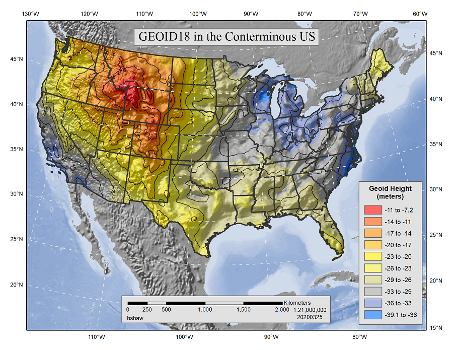
Figure 7. The hybrid geoid heights provided by GEOID18. Source: National Geodetic Survey
3. Vertical Datums in Geodesy
Common vertical datums include tidal, geodetic, and ellipsoidal. Each assumes a different zero reference surface. Tidal datums are local datums that are defined by observations of tidal variations over time at specific gauge stations (NOAA, 2000). Principal tidal datums in the United States include Mean Sea Level (MSL), Mean Low Water (MLW), Mean Lower Low Water (MLLW), Mean High Water (MHW), and Mean Higher High Water (MHHW). Tidal datums are defined by a Metonic cycle (tidal epoch) which has an approximately 19-year period. This cycle describes the period during which all phases of Earth’s Moon, Sun, and Earth are completed and have returned to a particular date in the calendar year. Technically speaking, a Metonic cycle is 6939.69 days, a difference of 0.31 days in 19 years (NGS, 2001). Averaging over this lengthy interval removes the random and periodic variations in tides that would occur over shorter period. Ideally, data on tide heights are recorded at individual tidal gauge stations during a tidal epoch and mathematically averaged to create MSL (see NOAA, 2000 for a detailed discussion of this process). Assuming MSL at a single tidal gauge station (e.g., Annapolis, MD) will provide accurate elevations for the localized area around that gauge station. While elevations can be accurately extended from the Annapolis, MD gauge station to distant places (e.g., Des Moines, IA), extending elevations from a different tidal gauge station only a few miles distant would produce observable elevation differences at Des Moines, which is one of the underlying problems exhibited by the NGVD29.
Vertical datums are based on an observed MSL at one or more points at some epoch. Geodetic survey methods (e.g., differential leveling) were used to transfer elevations from tidal gauge stations located along the coasts to interior parts of a region through setting BMs in the ground (Ghilani, 2016). Figure 8 illustrates differential leveling that begins by leveling a tripod so that the instrument’s telescope’s optical axis is perpendicular to gravity at the setup point. As a result, a level line is created at each survey point effectively leap-frogging a height from one location (benchmark 100’) along level lines to calculate a height 96’) at a distant location (BM). Geodetic leveling is recommended to between 50- to 100-meter line-of-sight lengths (depending on the desired survey order). Following this, leveling can produce accuracies that are sub-millimeter (over a kilometer in surveyed distance) in differential heights for a local geographic extent (NOAA, 2021). Although not as accurate as geodetic leveling, determining height via GNSS produces accuracies in the centimeter range. Presently, surveyors can use the National CORS Network (NCN) to control many of their heighting needs. The NCN provides active geodetic control data supporting 3-D positioning applications throughout the United States. Users who collect GNSS data can download NCN data for differential post-processing in their own software, or if certain requirements are met can use OPUS to automatically achieve similar results. Regardless of the method chosen for differential correcting with NCN data, the results are an improvement in accuracy and a true alignment to the NSRS. Properly collected GNSS data that is post-processed differentially alongside NCN data can approach coordinate accuracies of a few centimeters, both horizontally and vertically.
Figure 8. Differential leveling between a BM with a known elevation of 100’ and a BM with an unknown elevation at some distance. Source: NOAA Celebrates 200 Years of Science, Service, and Stewardship.
Reference ellipsoids are used to provide the means to convert X, Y, and Z coordinates into geodetic longitude, latitude, and height. For example, various GNSS satellite constellations (e.g., GPS – the official GNSS constellation of the United States) orbit Earth. United States satellites are tracked about using the World Geodetic System 1984 (WGS84) reference ellipsoid that has its origin at Earth’s geocenter, its center of mass. Exact knowledge of Earth’s geocenter and gravity field is determined by precisely recording the orbits of artificial satellites that orbit Earth. This information is used to create geodetic coordinate systems known as terrestrial reference frames (TRF). In general, a TRF can be described as a 3-D Earth-centered, Earth-fixed Cartesian coordinate system having three axes: X, Y, and Z (Figure 9). The X and Y axes define the equatorial plane and the Y axis is orthogonal to the X-axis. The plane defined by theZ- axis is the plane of the Prime Meridian. The Z-axis is nominally aligned with Earth’s polar axis. All three axes’ origins are orthogonal to one another and coincide with Earth’s geocenter, making the coordinate system Earth-centered. This XYZ coordinate system rotates with Earth, or, as the phrase suggests, Earth-fixed (see Meyer, 2010 and Torge and Müller 2012 for more information on TRFs).
Appropriate formulas described by Bowring (1976) are used to convert X, Y, and Z coordinates to f (latitude), l (longitude), and h (ellipsoid height). Given an ellipsoid height (h) and orthometric height (H) at a benchmark, rearranging Equation 1, one can determine the geoid height (N). As an aside, since f and l are reported as geodetic latitude and geodetic longitude, respectively, it would seem consistent if h were reported as geodetic height (Meyer, 2021b). However, for the moment, ellipsoid height is more commonly encountered in the literature.
Figure 9. The X-, Y-, and Z-axes of the Earth-centered, Earth-fixed Cartesian coordinate system. Source: author.
4. Classic, Transitional, and Modern Vertical Datums Used by the United States
Between 1888 and 1912, survey work extending from the Hudson River region continued generally along the 39th parallel of latitude to build a geodetic network that resulted in the Sea Level Datum,1929 (SLD29). The SLD29, later renamed to the National Geodetic Vertical Datum of 1929 (NGVD29) in 1973, was realized using 26 individual tide gauge stations scattered along the U.S. and Canadian coasts (21 in the United States and 5 in Canada). A total of 106,724 kilometers of leveling were involved developing NGVD29 (Berry, 1976).
4.1 A Classical Vertical Datum
To build NGVD29, the zero-elevation (the level surface) was held fixed, in a least squares sense, at each of the 26 gage stations. Ten of thousands of passive BMs were placed across CONUS to carry this implied level surface to the continent’s interior. In this manner, errors and inconsistencies were distributed throughout the geodetic network. Defining NGVD29 in this manner was problematic. Ocean currents, salinity, temperature, and other factors created non-identical heights at the gauge stations which implied that MSL or any other assumed geopotential surface cannot be held constant among gauge stations. By forcing a single geopotential surface at each of the 26 gauging stations, NGVD29 resulted in a “warped” datum meaning that biases were introduced into the vertical network, and did not directly address the difference in heights, for example, between the Pacific and Atlantic Oceans, MSL, or the geoid. In practice, NGVD29 did provide good local accuracy (less than a county level) but the accuracy diminished over larger spatial scales. The lack of known gravity data also factored into the development of NGVD29 and resulted in elevations derived from NGVD29 being called normal orthometric heights. Here, “normal” refers to the reduction of the leveling observations using the normal gravity equation that was available at the time. At the same time, ellipsoid heights (h) were similarly difficult to determine (Meyer et al., 2006).
4.2 A Transitional Vertical Datum
Since NGVD29's realization, a total of approximately 625,000 km of additional leveling benchmarks was added to the geodetic network’s densification that helped build NAVD88 (Zilkoski et al., 1992). Despite this additional leveling, an inventory of existing geodetic benchmarks by the NGS in the 1970s found that thousands of benchmarks had been destroyed or disturbed due to various activities such as highway construction, postglacial rebound, and subsidence resulting from the withdrawal of underground materials (Zilkoski et al., 1992). The deterioration of this passive BM network coupled with the inherent bias built into the forcing of 625,000 km of leveling to fit previously determined NGVD29 height values also became apparent. In addition, measurement and positional technologies (e.g., Very Long Baseline Interferometry (VLBI), Satellite Laser Ranging (SLR), GNSS, and Doppler Orbitography Radiopositioning Integrated on Satellite (DORIS)) improved the ability to establish accurate positions and elevations has exceeded the accuracy of the underlying geodetic network.
A vison for a new datum was proposed. Unlike the approach taken with NGVD29, a single level surface was selected at Father Point, Rimouski, Québec, Canada and held fixed. This gauge station was chosen, in part, due its existing use as a level surface for the International Great Lakes Datum 1955 (IGDL55). To create NAVD88, a new adjustment was carried out that involved approximately 505,000 permanent BMs, 204,000 temporary BMs, and 1.2 million observations. Figure 10 shows the range of height differences for CONUS between NAVD88 and to NGVD29 are from approximately -40 cm in Florida to +150 cm in the parts of the Rocky Mountains. In Alaska, the differences range from approximately +94 cm to +240 cm. However, in most "stable" areas of the U.S. interior such as Kansas, relative height changes between adjacent BMs are generally less than 1 cm.
Figure 10. The general height differences in cm between NGVD29 and NAVD88. Source: National Geodetic Survey
While NGVD29 published normal orthometric heights, NAVD88 reports Helmert orthometric heights and IGLD55 reports dynamic heights which are scaled geopotential numbers (C). Van Sickle (2017, 92) explains that C of a given point equates to the “difference between the geopotential below the point, down on a geoid, and the geopotential right at the point itself.” In other words, values of C focus more on a change in heights rather than absolute heights. Meyer et al (2006) state that values of C are expressed in geopotential units (gpu) where 1 gpu. = 1 kgal-meter and report units of energy, not length which makes them ill-suited to directly report height. Converting C to meters produces a dynamic height and is carried out by dividing C by some chosen gravity value (e.g., using the value of normal gravity at some latitude, usually 45°). Meyer (2010, 188) explains that using values of C to determine elevations offers the following four advantages: 1) if two points rest on the same geopotential surface, water will not flow between them, 2) values of C decrease with distance from Earth’s center, 3) values of C do not depend on the path taken from Earth’s center to the point in question, and 4) the geoid can be defined to have a C of zero. Helmert orthometric and dynamic heights are both re-expressions of C using different conversions. Hoffman-Wellenhof and Mortiz (2006) presents formulas to compute Helmert orthometric and dynamic heights that require the knowledge of, for example, the value of C and the surface gravity measurement (e.g., 980,619.9 mgals at a point. Gravity is quantified by the unit measurement known as gal where 1 gal is the acceleration of 1 cm per second2 which is the rate at which the velocity of a falling object changes. The value 980,619.9 mgals2 is the average acceleration of gravity at 45° latitude.
The NGS publishes geodetic control information that resides in their IDB (Integrated Database) via Datasheets that can be queried and downloaded using their Data Explorer or various other methods. Figure 11 shows a portion of a Datasheet for the mark having a Permanent ID (PID) of JY0129 from Athens, Ohio. From Figure 11, note that the published values for NAVD 88 ORTHO HEIGHT, GEOID HEIGHT, and DYNAMIC HEIGHT. The MODELED GRAVITY (expressed in mgals) are also reported.
Using appropriate formulas, orthometric and dynamic heights, for example, can be converted into a value of C. Note the difference between the various expressed height values, especially with respect to NGVD29.
Figure 11. A data sheet from NGS’ Data explorer showing various height values for station E 112, with a PID of JY0129 in Athens, OH. Source: National Geodetic Survey
4.3 A Modern Geopotential Datum
NAVD88 was realized from a passive network of BMs. A given BM can be 80 or more years old, are almost never re-checked for movement, disturbed by the thousands every year, or are often not ideally located for survey work. In addition, these BMs were leveled from a level surface held fixed at Father Point allowing unwanted cross-country error to accumulate. As a result of this, and other factors, NAVD88 has a “tilt” of about 1 meter from the Southeast to the Northwest CONUS (Figure 12). More importantly NAVD88 does not fully take advantage of the accuracy and timeliness that active GNSS data provides. For these reasons, NAVD88 is being replaced by a new vertical datum NAPGD2022.
Figure 12. The southeast to northwest tilt of NAVD88 in the lower 48 United States. The colors represent the “tilt” in meters. Source: National Geodetic Survey.
Smith et al. (2015) summarize the advantages of NAPGD2022 include direct access via GNSS and an accurate geoid model. The use of GNSS technology enables timely reporting of ellipsoid heights to a few cm in accuracy. Orthometric heights are commonly reported on maps and offer an intuitive understanding of how water flows. Ellipsoid heights do not necessarily have this connotation. However, compared to the availability of GNSS data, determining orthometric heights is only possible through leveling which can be very costly and time intensive. Orthometric heights can be computed with the same speed and accuracy as GNSS reports ellipsoid heights via an accurate geoid model. Developing an accurate geoid model (with accuracies near 1cm) coupled with GNSS data will enable orthometric heights to be determined that comes close to the millimeter accuracies that were possible using differential leveling. Moreover, GNSS will improve the efficiency of heighting by reducing the number of hours involved, specifically with the field occupation process. This increase in efficiency is part of NGS’ 10-Year Strategic Plan (NOAA, 2013, p. 10) to modernize and improve the NSRS to “reduce all definitional and access-related errors in orthometric heights in the geopotential reference frame to 2 centimeters when using 15 minutes of GNSS data.” Evidence from Kubodera et al. (2016, p. 56) supports the efficiency gained from GNSS data suggesting that, based on their research, the total observation hours of GNSS field data collection is "about one-fiftieth (1/50) that of direct leveling.”
While NAPGD2022 is being discussed here as a reference surface, it will be a component of the NSRS that includes both geometric coordinates (X, Y, and Z) and a geopotential model of Earth’s gravity. Figure 13 shows the approximate geographic extent of the NAPGD2022 geopotential datum. The “geopotential datum” label is deliberate as the reported data associated with NAPGD2022 will include geoid heights, geopotential number, acceleration of gravity, and other gravity-related information (NOAA, 2021). Once fully realized, NAPGD2022 will enable four capabilities: (1) define a geopotential datum via a geoid model (eventually with 1 cm of accuracy); (2) incorporate GNSS technology and GRAV-D; (3) provide timely, accurate, and consistent 2 cm orthometric heights everywhere in the United States and (4) create GEOID2022, a gravimetric geoid model, that will be the official zero-height surface for orthometric heights and will be modeled and monitored for changes over time. That being said, users’ reliance on passive BMs will be eliminated, as primary access to NAPGD2022 will be provided by NGS using the OPUS web portal.
Figure 13. The geographic extent of the GEOID2022 gravimetric geoid model for NAPGD2022. Source: National Geodetic Survey.
Replacing NAVD88 with NAPGD2022 is but one component of NGS’ overall mission to modernize and provide access to the NSRS for purposes of geospatial activities such as geodesy, land/hydrographic surveying, remote sensing, mapping, and charting. The NGS’ 2019-2023 Strategic Plan (NOAA, 2019) forwarded that modernizing the NSRS plays three critical roles to support the nation’s spatial needs. First, the NSRS will provide geodetic latitude, longitude, and height, in addition to orthometric height, geopotential numbers, acceleration of gravity and deflection of the vertical at any point within the United States or its territories using active geodetic control through, for example, GNSS. Second, the NSRS will provide information regarding its orientation and scale relative to international reference frames, as well as the precise orbits of all satellites used to define, realize, or access the NSRS for critical geodetic mapping projects. Third, the NSRS will provide the necessary information to describe how these quantities change over time providing accurate and timely positional information.
Amin, H., Lars S., and Mohammad B. (2019). "A global vertical datum defined by the conventional geoid potential and the Earth ellipsoid parameters." Journal of Geodesy, 93(10), 1943-1961. doi.org/10.1007/s00190-019-01293-3
Berry, R. (1976). History of geodetic leveling in the United States. American Congress on Surveying and Mapping, Bethesda, Maryland.
Bowring, B. (1976). “Transformation from spatial to geographical coordinates,” Survey Review, XXIII (181), 323-327.
Deakin, R. (1996) “The geoid what’s it got to do with me?”, Australian Surveyor, 41(4), 294-305. doi.org/10.1080/00050339.1996.10558646
Ewing, C., and Mitchell, M. (1970). Introduction to Geodesy. American Elsevier Publishing Co., Inc. New York, NY.
Joud, S. (2018). Contributions of satellite geodesy to post-glacial rebound research (Doctoral dissertation, KTH Royal Institute of Technology, TRITA-SoM 2018-02, 180 pp., Stockholm, Sweden).
Ghilani, C., Wolf, P., and Gidudu, A. (2021). Elementary surveying: An introduction to geomatics (16th ed.). Pearson-Prentice Hall, Upper Saddle River, New Jersey.
Hooijberg, M. (2008). Geometrical Geodesy: Using Information and Computer Technology. Springer, Heidelberg, Germany.
Kubodera, T., Okazawa, H., Hosokawa, Y., Kawana, F., Matsuo, E., and Mihara, M. (2016). “Effects of Surveying Methods between GNSS and Direct Leveling on Elevation Values over Longer Distance in Mountainous Area.” International Journal of Environmental and Rural Development, 7(1): 62-69. doi.org/10.32115/ijerd.7.1_62
Meyer, T., Roman, D., and Zilkoski , D. (2006). "What does height really mean? Part III: heightsystems," Department of Natural Resources and the Environment Articles. Paper 2. Available at http://digitalcommons.uconn.edu/nrme_articles/2
Meyer. T. (2021a). “Earth's Shape, Sea Level, and the Geoid.” The Geographic Information Science & Technology Body of Knowledge (2nd Quarter 2021 Edition), John P. Wilson (ed.). https://gistbok.ucgis.org/bok-topics/earths-shape-sea-level-and-geoid doi.org/10.22224/gistbok/2021.2.8
Meyer, T (2021b). Personal correspondence.
Meyer, T. (2010). Introduction to Geometrical and Physical Geodesy: Foundations of Geomatics. ESRI Press, Redlands, California.
Meyer, T., Roman, D., and Zilkoski, D. (2006). “What does height really mean? Part III: Height Systems.” Surveying and Land Information Science, 66(2), 149-160.
Milbert, D. G. (1991). “GEOID90: A high‐resolution geoid for the United States.” Eos, Transactions American Geophysical Union, 72(49), 545-554. doi.org/10.1029/EO072i049p00545-01
Moritz, H. (1980). Geodetic Reference System 1980. Bulletin Géodésique, 54(3), 395-405.
NGS. (2001). “Geodetic Glossary” from: https://www.ngs.noaa.gov/CORS-Proxy/Glossary/xml/NGS_Glossary.xml
NOAA. (2021). Blueprint for 2022, Part 2: Geopotential Coordinates. NOAA Technical Report NOS NGS 64. Available at: https://www.ngs.noaa.gov/PUBS_LIB/NOAA_TR_NOS_NGS_0064.pdf
NOAA. (2019). The National Geodetic Survey Strategic Plan 2019 – 2023 Positioning America for the Future. National Oceanic and Atmospheric Administration. U.S. Department of Commerce. Washington D.C. Available at: https://geodesy.noaa.gov/web/about_ngs/info/documents/ngs-strategic-plan-2019-2023.pdf
NOAA. (2013). The National Geodetic Survey Ten-Year Strategic Plan, 2013 – 2023 Positioning America for the Future. National Oceanic and Atmospheric Administration. U.S. Department of Commerce. Washington D.C. Available at: https://geodesy.noaa.gov/web/news/Ten_Year_Plan_2013-2023.pdf
NOAA (2000). Tidal Datums and Their Applications. NOAA Special Publication NOS CO-OPS 01. Department of Commerce. Silver Spring, Maryland. Available at https://tidesandcurrents.noaa.gov/publications/tidal_datums_and_their_applications.pdf
Pavlis, N., Holmes, S., Kenyon, S., and Factor, J., (2012). “EGM2008: The development and evaluation of the Earth Gravitational Model 2008 (EGM2008).” Journal of Geophysical Research: Solid Earth (1978-2012), 117(B4), April 2012. doi.org/10.1029/2011JB008916
Rapp, R., and Pavlis, N. (1990). “The development and analysis of geopotential coefficient models to spherical harmonic degree 360,” Journal of Geophysical Research: Solid Earth, 95(B13), 21885-21911. doi.org/10.1029/JB095iB13p21885
Roman, D. and Li, X. (2014). "GRAV–D: Using Aerogravity to Produce a Refined Vertical Datum." International Federation of Surveyors. Available at: http://fig.net/resources/monthly_articles/2014/september_2014/roman_li.pdf
Sánchez, L., Ågren, J., Huang, J., Wang, Y., Mäkinen, J., Pail, R., Barzaghi, R., Vergos, G., Ahlgren, K.and Liu, Q. (2021). “Strategy for the realisation of the International Height Reference System IHRS).” Journal of Geodesy, 95(3), 1-33. doi.org/10.1007/s00190-021-01481-0
Smith, D. and Milbert, D. (1999). The GEOID96 high-resolution geoid height model for the United States. Journal of Geodesy, 73(5), 219-236. doi.org/10.1007/s001900050239
Smith, D., Roman, D., and Childers, V. (2015). “Modernizing the Datums of the National Spatial Reference System.” Marine Technology Society Journal. 49(2), 151-158. doi.org/10.4031/MTSJ.49.2.20
Tapley, B. and Reigber, C. (2001, December). “The GRACE mission: status and future plans.” In AGU Fall Meeting Abstracts (Vol. 2001, pp. G41C-02).
Tapley, B., Watkins, M., Flechtner, F., Reigber, C., Bettadpur, S., Rodell, M., and Velicogna, I. (2019). Contributions of GRACE to understanding climate change. Nature Climate Change, 9(5):358-369. doi.org/10.1038/s41558-019-0456-2
Torge, W and Muller, J. (2012). Geodesy (4th ed.). De Gruyter, Berlin, Germany.
Van Sickle, J. (2017). Basic GIS Coordinates. 3rd edition. CRC Press, Boca Raton, Florida.
Zenk, D. (2014). “Correct Use of NAD83 Realizations and GEOID Models.” Minnesota Surveyor. 22(3):16-18.
Zilkoski, D., Richards, J. and Young, G. (1992). “Special Report Results of the General Adjustment of the North American Vertical Datum of 1988.” Surveying and Land Information Systems, 52(3), 133-149.
Keywords: