database design

DM-33 - Modeling tools
  • Compare and contrast the relative merits of various textual and graphical tools for data modeling, including E-R diagrams, UML, and XML
  • Create E-R and UML diagrams of database designs
  • Create conceptual, logical, and physical data models using automated software tools
DM-34 - Conceptual Data Models
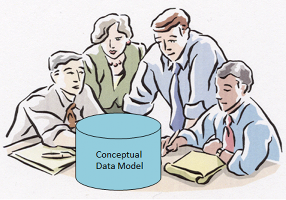
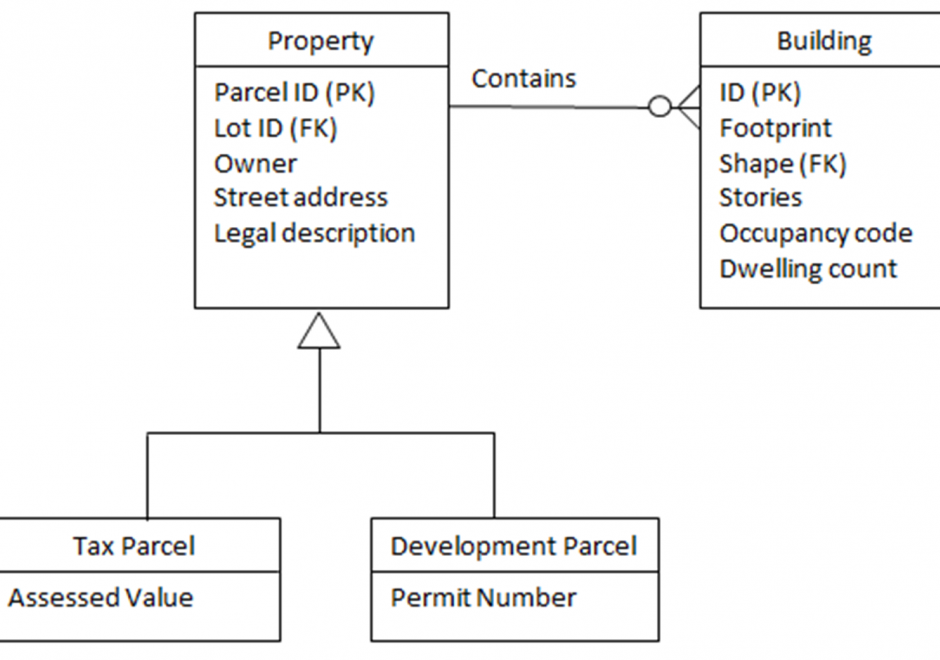
Within an initial phase of database design, a conceptual data model is created as a technology-independent specification of the data to be stored within a database. This specification often times takes the form of a formalized diagram.  The process of conceptual data modeling is meant to foster shared understanding among data modelers and stakeholders when creating the specification.  As such, a conceptual data model should be easily readable by people with little or no technical-computer-based expertise because a comprehensive view of information is more important than a detailed view. In a conceptual data model, entity classes are categories of things (person, place, thing, etc.) that have attributes for describing the characteristics of the things.  Relationships can exist between the entity classes.  Entity-relationship diagrams have been and are likely to continue to be a popular way of characterizing entity classes, attributes and relationships.  Various notations for diagrams have been used over the years. The main intent about a conceptual data model and its corresponding entity-relationship diagram is that they should highlight the content and meaning of data within stakeholder information contexts, while postponing the specification of logical structure to the second phase of database design called logical data modeling. 

DM-35 - Logical Data Models

A logical data model is created for the second of three levels of abstraction, conceptual, logical, and physical. A logical data model expresses the meaning context of a conceptual data model, and adds to that detail about data (base) structures, e.g. using topologically-organized records, relational tables, object-oriented classes, or extensible markup language (XML) construct  tags. However, the logical data model formed is independent of a particular database management software product. Nonetheless such a model is often constrained by a class of software language techniques for representation, making implementation with a physical data model easier. Complex entity types of the conceptual data model must be translated into sub-type/super-type hierarchies to clarify data contexts for the entity type, while avoiding duplication of concepts and data. Entities and records should have internal identifiers. Relationships can be used to express the involvement of entity types with activities or associations. A logical schema is formed from the above data organization. A schema diagram depicts the entity, attribute and relationship detail for each application. The resulting logical data models can be synthesized using schema integration to support multi-user database environments, e.g., data warehouses for strategic applications and/or federated databases for tactical/operational business applications.

DM-36 - Physical Data Models

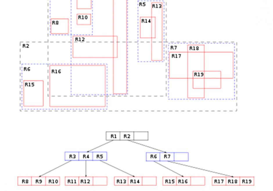
Constructs within a particular implementation of database management software guide the development of a physical data model, which is a product of a physical database design process. A physical data model documents how data are to be stored and accessed on storage media of computer hardware.  A physical data model is dependent on specific data types and indexing mechanisms used within database management system software.  Data types such as integers, reals, character strings, plus many others can lead to different storage structures. Indexing mechanisms such as region-trees and hash functions and others lead to differences in access performance.  Physical data modeling choices about data types and indexing mechanisms related to storage structures refine details of a physical database design. Data types associated with field, record and file storage structures together with the access mechanisms to those structures foster (constrain) performance of a database design. Since all software runs using an operating system, field, record, and file storage structures must be translated into operating system constructs to be implemented.  As such, all storage structures are contingent on the operating system and particular hardware that host data management software. 

DM-36 - Physical models
  • Differentiate between logical and physical models, in terms of the level of detail, constraints, and range of information included
  • Create physical model diagrams, using UML or other tools, based on logical model diagrams and software requirements
  • Create a complete design document ready for implementation
  • Recognize the constraints and opportunities of a particular choice of software for implementing a logical model
DM-35 - Logical models
  • Determine which relationships need to be stored explicitly in the database
  • Create logical models based on conceptual models and general data models using UML or other tools
  • Differentiate between conceptual and logical models, in terms of the level of detail, constraints, and range of information included
  • Evaluate the various general data models common in GIS&T for a given project, and select the most appropriate solutions
  • Distinguish between the incidental and structural relationships found in a conceptual model
  • Explain the various types of cardinality found in databases
  • Define the cardinality of relationships
DM-34 - Conceptual models
  • Define entities and relationships as used in conceptual data models
  • Create a conceptual model diagram of data needed in a geospatial application or enterprise database
  • Design application-specific conceptual models
  • Deconstruct an application use case into conceptual components
  • Explain the objectives of the conceptual modeling phase of design
  • Describe the degree to which attributes need to be modeled in the conceptual modeling phase
DM-33 - Modeling tools
  • Compare and contrast the relative merits of various textual and graphical tools for data modeling, including E-R diagrams, UML, and XML
  • Create E-R and UML diagrams of database designs
  • Create conceptual, logical, and physical data models using automated software tools
DM-36 - Physical models
  • Differentiate between logical and physical models, in terms of the level of detail, constraints, and range of information included
  • Create physical model diagrams, using UML or other tools, based on logical model diagrams and software requirements
  • Create a complete design document ready for implementation
  • Recognize the constraints and opportunities of a particular choice of software for implementing a logical model
DM-35 - Logical models
  • Determine which relationships need to be stored explicitly in the database
  • Create logical models based on conceptual models and general data models using UML or other tools
  • Differentiate between conceptual and logical models, in terms of the level of detail, constraints, and range of information included
  • Evaluate the various general data models common in GIS&T for a given project, and select the most appropriate solutions
  • Distinguish between the incidental and structural relationships found in a conceptual model
  • Explain the various types of cardinality found in databases
  • Define the cardinality of relationships

Pages